
Working principle and structure of torsion testing machine
Working Principle and Structure of a Torsion Testing Machine
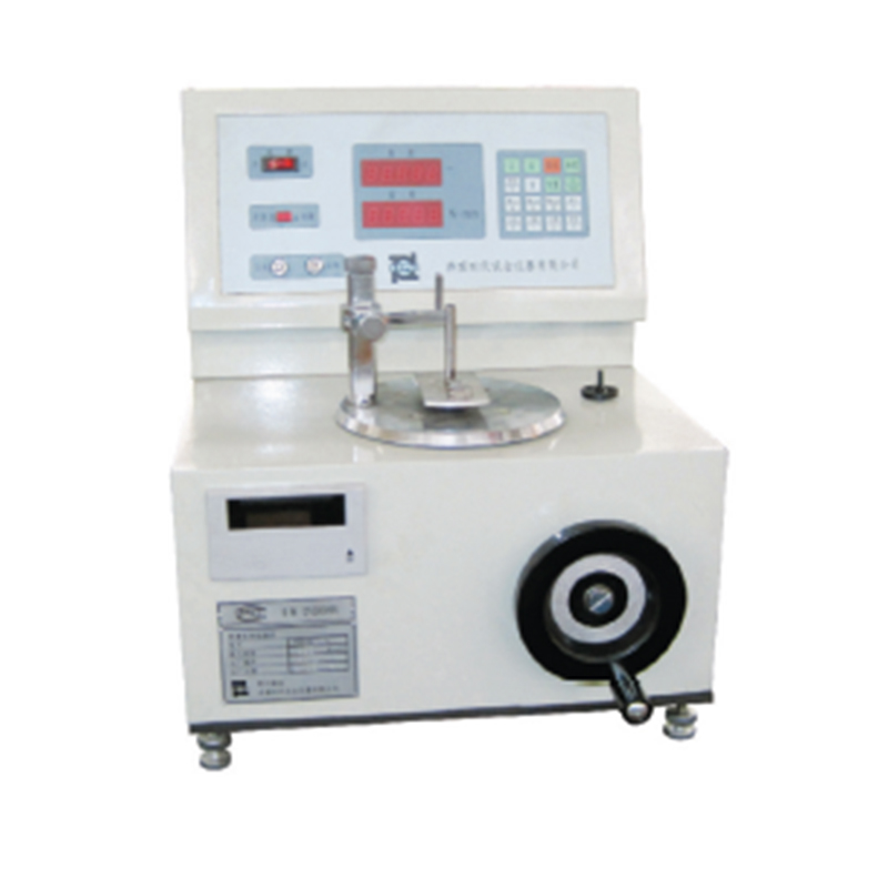
The electric material torsion testing machine consists of two main parts: mechanical and electrical. Its working principle is as follows: The electric material torsion testing machine uses electric loading. The sensor and sensor support on the left can move left and right for easy specimen clamping. During torsion loading, a fully digital AC servo motor drives the clamps to rotate via a precision planetary gear reducer to load the specimen, thus achieving the torsion test.
The center of the worktable is the workpiece torsion space, consisting of a fixed clamp (left) and a rotating clamp (right) for specimen clamping.
The main control panel of the electric material torsion testing machine is engraved with power indicators such as "Left-hand" and "Right-hand," as well as a red emergency stop button, allowing manual operation of left-hand and right-hand rotation during experiments.
If the testing machine malfunctions or encounters a sudden emergency, the emergency stop button should be pressed immediately to ensure the machine is in self-protection mode and stops working.
Main Applications:
This series of testing machines is mainly applicable for testing the torsion angle and torque of various kinds ofsmallsized torsion springs, coil springs, elastic components and other friction structures.
● Vertical clamping, avoid the non-negligible friction force for small-sized springs.
● The torsion angle and torque are both digitally displayed.
● Manual loading, rotation direction can be either left or right.
● Compact in mechanism, easy to operate, and quick to test.